


High Performance Overhead Ground Wire Solutions for Power Grids
High-voltage electrical transmission systems form the backbone of global energy distribution, spanning thousands of kilometers across diverse geographic regions, mountains, forests, and urban corridors. These exposed overhead infrastructure assets operate under severe environmental conditions and are continuously subjected to atmospheric phenomena, including direct lightning strikes, severe wind loads, ice accumulation, and extreme temperature fluctuations. To maintain structural integrity and protect expensive sub-station transformers, circuit breakers, and insulator strings from high-energy surge currents, modern electrical utilities rely on high-integrity protective conductors installed at the top of transmission towers. An overhead ground wire is a critical component engineered to shield energised phase conductors from atmospheric discharges while providing a low-impedance path to route fault currents safely into the earth.
Positioned strategically above the primary phase conductors on transmission towers and distribution poles, the protective ground conductor acts as an electro-geometric shield. During a lightning event, atmospheric static discharges naturally strike the highest physical point along the transmission corridor. By intercepting these direct lightning strikes, the grounded wire prevents high-voltage surges from attaching directly to the live phase wires, which would otherwise cause line flashovers, insulation breakdown, phase-to-phase short circuits, and widespread power grid blackouts. Additionally, during system line-to-ground fault conditions—such as when a phase conductor contacts a tree branch or structural element—the grounded top conductor serves as a continuous metallic return path back to the system neutral at the substation, facilitating rapid relay detection and circuit breaker interruption.
Understanding the engineering requirements of overhead protective conductors requires evaluating both electrical and mechanical stresses. The conductor must possess sufficient current-carrying capacity to withstand short-duration, high-magnitude lightning impulse currents and short-circuit fault currents without undergoing severe thermal degradation or melting. Mechanically, it must exhibit high breaking strength, low thermal expansion, high creep resistance, and excellent fatigue endurance under continuous wind-induced vibrations. Over decades of operational service, the physical composition of shielding wires has evolved from basic galvanized steel to advanced composite metallurgies, with aluminum-clad steel representing one of the most widely adopted materials across modern utility grids.
Metallurgical Engineering and Material Specifications of Aluminum Clad Steel
The development of Aluminum Clad Steel (ACS) conductors represents a major advancement in wire and cable engineering for power distribution and transmission line protection. Traditional galvanized steel wires provide high mechanical tensile strength but suffer from relatively high electrical resistance and susceptibility to surface corrosion over long operational lifespans. As industrial activity and coastal exposure accelerate atmospheric corrosion, zinc coatings on traditional galvanized steel wires gradually degrade, exposing the underlying steel core to rust, mechanical weakening, and eventual failure.
Aluminum Clad Steel wire overcomes these operational limitations through a specialized manufacturing process that applies a continuous, seamless layer of high-conductivity, commercially pure aluminum over a high-carbon steel core wire. Rather than relying on simple mechanical plating or electroplating, the cladding process creates a permanent atomic metallurgical bond between the aluminum outer sheath and the high-strength steel core. This metallurgical bond ensures that the outer aluminum layer and inner steel core expand, contract, bend, and flex as a unified structural material without peeling, flaking, cracking, or delaminating during high-tension installation or decades of continuous environmental exposure.
The electrical conductivity of ACS wire is determined by the volumetric proportion of the high-purity aluminum layer relative to the high-tensile steel core. Standard industry specifications classify ACS conductors primarily into 20.3% IACS (International Annealed Copper Standard) and 40% IACS conductivity grades. A 20.3% IACS conductor utilizes a cladding layer thickness representing approximately 10% of the wire radius, providing a balanced combination of extreme tensile strength and adequate conductivity. A 40% IACS conductor features a thicker aluminum cladding layer, offering significantly lower direct current (DC) and alternating current (AC) electrical resistance, making it ideal for transmission corridors subject to high short-circuit fault current levels.
The metallurgical synergy of aluminum and steel provides distinct structural performance advantages. The inner high-carbon steel core delivers exceptional tensile strength, allowing the wire to withstand high mechanical tensions, long span lengths, heavy ice accumulation, and high wind velocity pressures. Meanwhile, the seamless outer aluminum layer isolates the steel core completely from atmospheric moisture, oxygen, sulfur dioxide, industrial chemical pollutants, and airborne marine salt spray. Because aluminum forms a self-passivating oxide film upon exposure to air, the outer cladding remains highly resistant to atmospheric corrosion, ensuring sustained mechanical breaking load and predictable electrical conductivity over design lifespans exceeding fifty years.
Electro-Geometric Shielding and High-Voltage Transient Management
The placement and geometric orientation of an overhead ground wire atop high-voltage transmission towers are governed by rigorous electro-geometric design models (EGM). Line design engineers analyze lightning flash density maps, tower height geometry, terrain elevation, and conductor bundle arrangements to establish an optimal shielding angle. The shielding angle is defined as the angle formed between a vertical line passing through the ground conductor and an inclined line connecting the ground wire to the outermost phase conductor.
Typically, utilities maintain shielding angles ranging between 15 degrees and 30 degrees, depending on tower height, terrain contouring, and local lightning intensity. A narrower shielding angle provides a broader protective envelope, significantly reducing the probability that a lightning streamer will bypass the top protective conductor and strike an exposed phase conductor directly—an event known as a shielding failure. On extra-high-voltage (EHV) and ultra-high-voltage (UHV) transmission lines built with taller lattice structures and longer cross-arms, utilities frequently install two parallel ground wires positioned on twin tower peaks to maintain an effective shielding zone across wide multi-conductor phase bundles.
When a lightning strike attaches to the shield wire, an intense electrical current surge—often exceeding 50,000 to 100,000 amperes with rise times measured in microseconds—travels rapidly in both directions along the conductor toward adjacent support structures. At each transmission tower, a portion of this surge current flows down the metallic tower legs and dissipates into the surrounding earth through engineered ground rod arrays and counterpoise grounding conductors. The electrical impedance of the shield wire, combined with the tower footing resistance, determines the transient peak voltage developed on the tower structure. If the tower structure voltage exceeds the basic impulse insulation level (BIL) of the line insulator assemblies, a reverse breakdown known as a back-flashover can occur from the tower structure back to the phase conductor.
To minimize the risk of back-flashover events, power line engineers specify lower DC electrical resistance ground wire materials such as aluminum-clad steel. Lower electrical resistance reduces the voltage drop along the ground line during surge propagation. Furthermore, during system line-to-ground faults caused by equipment breakdown or atmospheric flashovers, high-conductivity ACS stranded conductors handle large short-circuit fault currents (measured in kiloamperes over durations ranging from 0.5 to 1.0 seconds) without exceeding critical thermal annealing thresholds. Excess heat generated during short-circuit faults can cause unclad steel to lose its heat treatment temper, leading to permanent loss of tensile strength and mechanical sagging. The superior thermal conductivity and heat dissipation capacity of the aluminum cladding mitigate localized hot spots, preserving the mechanical integrity of the entire cable assembly under severe electrical fault conditions.
Mechanical Dynamics, Sag-Tension Behavior, and Aerodynamic Stability
Beyond its primary electrical protective functions, an overhead ground wire must perform under continuous, complex mechanical loading conditions. High-voltage transmission corridors traverse varied topography, subjecting span lengths ranging from a few hundred meters to over a kilometer to complex environmental forces. Power utilities conduct detailed sag-tension calculations using specialized software to ensure that protective top wires maintain proper mechanical clearance above underlying phase conductors under all operational temperature ranges and climatic loading combinations.
The mechanical tension of the top protective wire is tightly correlated with the tension of the underlying phase conductors. In typical utility designs, the ground conductor is strung with slightly less sag than the phase conductors under normal operating conditions. This design practice ensures that as ice accumulates on all cables across a span or as high ambient temperatures cause thermal expansion, the vertical clearance between the top shield wire and the energised phase wires remains within safe electrical breakdown safety margins. If the top shield wire were to sag excessively relative to the phase conductors, mid-span clearance would be compromised, posing severe risks of inter-conductor galloping, flashover, or physical collision during wind storms.
Mechanical dynamics on long-span overhead cable systems include micro-vibrations and macro-oscillations caused by aerodynamic forces. Aeolian vibration is a high-frequency, low-amplitude standing wave phenomenon caused by steady, low-velocity laminar winds passing across stranded smooth-surface conductors. As wind flows around the circular profile of the stranded cable, alternating vortices shed from the top and bottom surfaces, producing periodic transverse aerodynamic lift forces. If the vortex shedding frequency matches the natural resonant frequency of the tensioned wire span, standing waves develop, inducing cyclic bending stresses at suspension clamps and tower attachment points. Left unmitigated, repetitive bending stresses cause mechanical metal fatigue, leading to individual wire strand breakage near support fittings.
To combat aeolian vibration fatigue, line engineers integrate specialized vibration control hardware along the ground line. Stockbridge dampers—consisting of two asymmetric metallic weights attached to a flexible stranded steel messenger cable locked with a central clamp—are installed on the ground wire adjacent to suspension clamps. These dampers absorb and dissipate dynamic mechanical energy through inter-strand friction within the messenger cable. Additionally, spiral armor rods and reinforced suspension grips are applied over the ACS conductor at attachment points to distribute localized bending stresses over a broader surface area, preventing concentrated mechanical stress risers from damaging the aluminum cladding or steel wire strands.
In addition to high-frequency aeolian vibration, overhead line corridors face sub-span oscillations and low-frequency, high-amplitude cable galloping. Galloping occurs primarily under combination weather conditions where freezing rain creates an asymmetrical ice profile on the wire surface, acting like an aerodynamic airfoil under high crosswind conditions. The high modulus of elasticity and high breaking strength of aluminum-clad steel strands provide superior mechanical resistance against tensile shock loads generated by violent galloping motions, safeguarding line structural stability during extreme winter weather occurrences.
Multi-Strand Construction Configurations and Industry Manufacturing Standards
Manufacturing continuous high-reliability protective conductors requires adherence to strict international dimensional, mechanical, and electrical standards. Aluminum Clad Steel ground wires are fabricated in various multi-strand configurations tailored to specific system mechanical loading requirements and fault current levels. Single solid ACS wires are frequently used in distribution networks and communication line guyings, whereas stranded conductor constructions are essential for high-voltage and extra-high-voltage transmission lines.
Common multi-strand conductor configurations include 3-strand, 7-strand, 19-strand, and 37-strand concentric-lay constructions:
-
3-strand ACS constructions feature three individual aluminum-clad steel wires twisted helically together, offering a lightweight, high-strength solution for shorter span lengths and lower fault current requirements.
-
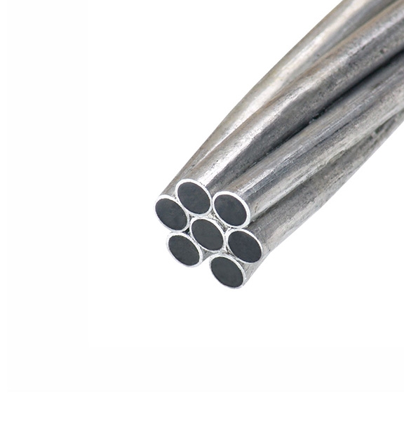
7-strand ACS constructions consist of a single central core wire surrounded by six helically wrapped outer wires. This configuration represents one of the most widely specified utility ground wires globally, striking an optimal balance between mechanical breaking strength, overall cable flexibility, and current-carrying capacity.
-
19-strand ACS constructions utilize two concentric layers of wires over a central core (a 1-6-12 geometry), providing higher cross-sectional aluminum area, lower electrical resistance, and elevated tensile breaking loads for long-span river crossings and EHV line applications.
-
37-strand ACS constructions feature three concentric layers over a core wire, yielding very large conductive cross-sections capable of carrying extreme short-circuit fault currents in heavy industrial grid hubs.
Manufacturing processes must comply with internationally recognized technical specifications, such as ASTM B415 (Standard Specification for Aluminum-Clad Steel Wire for Electrical Purposes), ASTM B416 (Standard Specification for Concentric-Lay-Stranded Aluminum-Clad Steel Conductors), DIN 48201, and GB/T 1179. These standards dictate precise tolerances regarding individual wire diameter uniformity, minimum aluminum cladding thickness, minimum tensile breaking strength in megapascals (MPa), maximum direct-current resistance at 20 degrees Celsius, and minimum elongation percentages.
During production quality assurance, samples from every production reel undergo rigorous mechanical and electrical testing. Tensile testing verifies that the stranded cable meets or exceeds specified rated strength values (often exceeding 100 to 600 kilonewtons depending on cable diameter and strand count). Torsion tests and wrap tests are conducted on individual wires to confirm that the metallurgical bond between the aluminum layer and steel core remains uncompromised under extreme mechanical twisting and tight-radius bending. DC resistance measurements verify that electrical conductivity complies strictly with the specified IACS percentage rating, ensuring predictable operational performance once installed in utility networks.
Packaging and logistics also play a vital role in preserving conductor quality prior to installation. Stranded ground wires are wound under controlled tension onto heavy-duty steel, wooden, or steel-wooden hybrid reels. Packaging drums are sealed with protective wrappings to shield the stranded wire from physical abrasion, moisture accumulation, and chemical exposure during international ocean freight transport and rural field staging.
Advanced Hybrid Configurations and Grid Communication Integration
As utility grids undergo continuous modernization and infrastructure upgrades, the traditional protective overhead ground wire has evolved beyond its primary electro-geometric shielding role to encompass high-speed communications infrastructure. Modern electric power transmission networks require real-time monitoring, automated tele-protection relaying, Supervisory Control and Data Acquisition (SCADA) communication, and high-capacity data exchange between substations and central utility control centers.
To meet these dual requirements of electrical protection and optical communications, utility networks widely deploy Optical Ground Wire (OPGW) technology. An OPGW cable is a specialized composite conductor that combines the protective electrical and mechanical capabilities of an aluminum-clad steel ground wire with embedded optical fiber assemblies. The central core or inner layer of an OPGW cable contains one or more hermetically sealed stainless steel tubes or aluminum tubes housing multiple single-mode optical fibers. Surrounding these optical fiber units are one or more outer layers of stranded aluminum-clad steel wires and high-conductivity aluminum alloy wires.
The outer stranded metal layers of an OPGW cable fulfill the traditional duties of the grounded top wire: intercepting direct lightning strikes, carrying short-circuit fault currents back to substations, and withstanding continuous environmental wind and ice tensions. Meanwhile, the internal optical fibers provide an ultra-high-speed, high-bandwidth data transmission pathway completely immune to electromagnetic interference (EMI), radio frequency interference (RFI), corona discharge, and high-voltage induction generated by adjacent power phase conductors.
Because glass optical fibers transmit data via light pulses rather than electrical signals, they offer complete galvanic isolation between transmission towers and substations. This optical isolation eliminates ground potential rise issues during high-voltage fault events, ensuring uninterrupted communication for critical protection relays that trip circuit breakers within milliseconds during line faults. The combination of high-strength ACS outer stranding and internal fiber optic units delivers a dual-function solution that optimizes transmission line right-of-way usage, eliminates the need for separate communication line construction, and dramatically reduces overall capital expenditure for power utilities.
Field Installation Procedures, Hardware Integration, and Asset Management
Installing an overhead ground wire along high-voltage transmission lines requires specialized stringing equipment, precise tension management, and purpose-engineered pole line hardware. Cable installation is typically executed using controlled tension stringing techniques to prevent the stranded wire from contacting the ground, rocks, vegetation, or structural steelwork, which could scratch the outer smooth aluminum cladding surface and introduce localized stress risers or corrosion initiation points.
Tension stringing machinery includes hydraulic pullers, tensioners, payout stands, and specialized anti-twisting swivels. During the pulling process, the wire is drawn through smooth, neoprene-lined stringing sheaves suspended from tower cross-arms. Maintaining continuous, uniform tension prevents the formation of wire bird-caging—a condition where outer stranded layers unlay and separate from inner layers—and prevents dangerous mechanical snap-backs. Once the wire is pulled through a designated line section, sag-tension measurements are verified using optical surveying instruments or dynamometers before the conductor is permanently dead-ended and clipped into suspension assemblies.
Hardware fittings used to secure ground conductors must match the exact mechanical strength and metallurgical composition of the wire to avoid bimetallic galvanic corrosion and mechanical stress concentration. Key attachment hardware components include:
-
Preformed dead-end grips and bolted tension clamps: Applied at anchor towers, angle structures, and terminal substations to transfer high tension loads directly to the tower framework.
-
Suspension clamps and trunnion assemblies: Installed at intermediate tangent towers to support the vertical weight of the wire span while allowing smooth angular articulation during wind deflection.
-
Parallel groove (PG) clamps and grounding jumpers: Provide secure electrical connections between the stranded ground wire and the tower steelwork or grounding down-lead conductors, ensuring a continuous low-resistance path to earth.
-
Stockbridge vibration dampers and armor rods: Installed adjacent to support hardware to mitigate high-frequency aeolian vibration stresses.
Long-term asset management and field maintenance protocols ensure that overhead protective wires maintain structural and electrical integrity over multi-decade service lifespans. Utility maintenance teams perform regular visual and thermographic inspections using unmanned aerial vehicles (UAVs), helicopter line patrols, and ground-based thermal imaging cameras. Infrared thermography detects localized hot spots caused by loose, oxidized, or high-resistance electrical grounding connections at tower tops. Early detection allows maintenance crews to retorque hardware or replace corroded connection jumpers before an atmospheric lightning event leads to tower attachment failure or insulator flashover.
Visual inspection routines monitor for physical conductor damage, strand fatigue, hardware looseness, ice accretion, and clearance encroachment from vegetation. In coastal or heavily polluted industrial corridors, periodic washing or detailed structural sampling of ACS wires helps verify that the outer aluminum cladding remains intact and uncompromised. For OPGW composite cables, optical time-domain reflectometers (OTDR) are periodically utilized to test optical fiber attenuation and locate micro-bends or stress points along the communication line, ensuring uninterrupted grid protection and data transmission performance.
Utility Infrastructure Investment and Life-Cycle Grid Economics
From an economic and operational perspective, investing in premium-grade protective conductors represents a highly cost-effective strategy for electric power utilities, transmission system operators (TSOs), and industrial infrastructure developers. High-voltage transmission lines represent massive capital investments running into millions of dollars per kilometer. A single unmitigated lightning strike attaching to an unshielded phase conductor can cause catastrophic failure of power transformers, circuit breakers, surge arresters, and line insulators at connected substations—resulting in repair costs that far exceed the price of installing high-specification top protection wires.
Moreover, unplanned power transmission outages severely impact grid reliability metrics, such as System Average Interruption Duration Index (SAIDI) and System Average Interruption Frequency Index (SAIFI). Power outages interrupt industrial production, commercial operations, and municipal infrastructure, causing substantial financial losses and regulatory penalties for utility companies. By installing continuous, highly reliable aluminum-clad steel grounding conductors along transmission corridors, utilities shield vital electrical assets against direct atmospheric strikes and establish dependable fault dissipation paths that keep power flowing reliably.
The long-term durability of Aluminum Clad Steel conductors further enhances life-cycle utility economics. Compared to standard galvanized steel wires that may require replacement every 15 to 20 years due to progressive zinc oxidation and rust corrosion, ACS conductors provide maintenance-free operation matching or exceeding the 50-year design life of the transmission towers themselves. The permanent metallurgical bond between the aluminum cladding and steel core prevents internal corrosion, maintaining constant mechanical breaking strength and stable DC electrical resistance throughout decades of operational service.
Whether deployed in new high-voltage line construction, grid interconnectors, long river crossing spans, or regional utility modernization projects, selecting engineered protective conductors ensures superior grid resilience, reduced maintenance overheads, and long-term asset protection.
Final Thoughts
The reliable operation of modern power transmission grids depends heavily on effective shielding and fault current management. High-performance aluminum-clad steel protective conductors deliver an exceptional balance of mechanical strength, electrical conductivity, and long-term corrosion resistance. By shielding phase conductors against direct atmospheric lightning strikes and providing a dependable return path for system fault currents, these essential wire and cable products safeguard critical utility infrastructure, prevent costly power outages, and support continuous electrical grid stability across diverse environmental landscapes.