


Optical Surface Technology in Lamp Mold Production
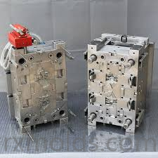
Vehicle lighting components often combine optical functions, structural features, and demanding appearance requirements within a relatively complex geometry. For this reason, an OEM Automotive Lamp Mold must be designed around more than basic cavity shape. Material flow, optical details, cooling, ejection, surface quality, and dimensional stability all need to be considered as part of one integrated tooling system.
The development process starts with the product design. Automotive lamp components can include lenses, reflectors, housings, bezels, light guides, and protective covers. Depending on their function, these parts may contain curved surfaces, thin sections, mounting structures, ribs, clips, sealing interfaces, and fine optical patterns. Each feature can influence the mold structure and the way material fills and cools inside the cavity.
Material selection should be evaluated together with the component geometry. Different polymers have different flow characteristics, shrinkage behavior, thermal properties, and surface requirements. Transparent materials used for optical components require careful cavity preparation, while structural materials may place greater emphasis on strength, impact resistance, or dimensional stability. Understanding these differences helps engineers develop suitable tooling and processing strategies.
Mold flow analysis can help evaluate the design before physical tooling is manufactured. Engineers can study potential filling imbalance, weld-line formation, air entrapment, pressure distribution, and other conditions. The findings can then support decisions about gate locations, runner layouts, venting, and cavity design. Early simulation can provide useful guidance before machining resources are committed to the final mold.
Optical features require particular precision because they can directly influence light distribution. A lens or light guide may contain fine patterns or carefully defined surfaces that must be reproduced accurately in the molded part. CNC machining can establish complex cavity geometry, while EDM can produce certain detailed features. Additional grinding and polishing processes may be used when the application requires a controlled optical or cosmetic surface.
Cavity surface preparation should be consistent across critical regions. An optical surface may require a highly controlled finish, while an exterior cosmetic area may need a specified texture or polished appearance. The finishing approach should be determined according to the component requirements and considered during mold design rather than treated as an isolated final operation.
Thermal management is also essential for stable injection molding. Once the polymer enters the cavity, the mold must remove heat in a controlled manner. Uneven thermal conditions can contribute to warpage, dimensional variation, and residual stress. Cooling channels should therefore be designed according to the component's wall thickness, geometry, and material characteristics.
Venting provides another important path for process control. Air displaced by incoming polymer needs to leave the cavity efficiently. If air remains trapped, it can contribute to burn marks, incomplete filling, or localized surface defects. Venting should be positioned based on the expected material flow while avoiding interference with important optical and visible surfaces.
Ejection mechanisms need to provide reliable part release without damaging the molded component. Lamp parts may contain delicate edges, deep structures, thin walls, or curved surfaces. Ejector pins, sleeves, lifters, and other release mechanisms should be arranged according to the component structure. Adequate draft angles can further reduce demolding resistance.
Precision inspection provides verification throughout the tooling process. Cavity and core dimensions, mold alignment, moving mechanisms, cooling passages, and surface conditions can all influence final component quality. During trial molding, sample parts can be evaluated for dimensions, appearance, filling behavior, ejection, and assembly compatibility. This information allows engineers to distinguish between tooling issues and processing-related factors.
A coordinated manufacturing workflow can improve development efficiency. CAD provides the foundation for mold geometry, CAE supports filling and thermal analysis, and CAM connects approved designs with machining operations. Integrating these systems with practical tooling experience helps maintain consistency between product requirements and physical mold construction.
Long-term performance also depends on mold maintenance. Repeated production cycles expose cavities, moving components, cooling systems, and alignment features to mechanical and thermal conditions. Periodic inspection can help identify wear or changes before they influence molded parts. Proper maintenance planning is therefore part of responsible tooling management rather than simply a response to production problems.
For manufacturers developing original equipment vehicle lighting components, Taizhou Renxin Mould Co., Ltd. combines engineering design, simulation, precision machining, surface finishing, and tooling validation, with further information available at https://www.rxmolds.com for organizations considering an OEM Automotive Lamp Mold for complex automotive lighting applications.