


Linear Slides for CNC and Industrial Equipment
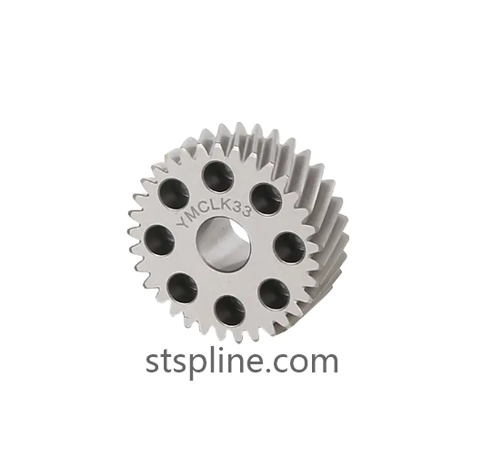
Industrial equipment often needs to move a carriage, cutting head, robot assembly, or other working structure along a predetermined path. A Rack And Pinion Linear Slide combines a toothed rack and rotating pinion with a suitable guide and support structure to create this type of controlled movement. The rack converts rotary input into linear travel, while the guide components maintain the moving assembly along its intended path. This configuration is suitable for many CNC, automation, robotics, and material handling applications.
The operating principle is straightforward but requires accurate mechanical coordination. A motor or gearbox drives the pinion, and the pinion teeth engage with the rack teeth. As rotation continues, the pinion moves along the rack and carries the attached assembly in a linear direction. The guide system supports the load and controls the movement path. Because the transmission and guide components share the mechanical load, their relative positioning is important to the complete slide design.
Material selection affects both manufacturing and service performance. Engineering steels and other suitable metals can be selected according to the machine's operating requirements. Factors such as machinability, structural strength, surface characteristics, and resistance to repeated contact should be considered. The rack and pinion should be produced as compatible transmission components, with their material and surface characteristics suitable for the expected operating environment.
Accurate tooth geometry is essential to smooth rack transmission. Consistent pitch and tooth profile allow the pinion to maintain stable engagement as it travels along the rack. Modern machining methods can control tooth dimensions and reduce variation across the working length. For extended linear slides, this consistency becomes particularly important because the pinion may travel across a long rack or several connected rack sections.
The guide arrangement determines how the moving carriage is supported. Depending on the equipment design, rollers, guide rails, linear bearings, or other guidance systems may be used. The guide structure should maintain the correct relationship between the moving assembly, rack, and pinion. If the guide path is not properly aligned, uneven forces may be introduced into the transmission and affect tooth contact.
Long travel is one area where rack-based slides can provide useful design flexibility. Large CNC machines, laser cutting equipment, automated storage systems, and production-line machinery may require movement over considerable distances. Multiple rack sections can be positioned along a common axis when a longer travel path is needed. The section joints should be aligned carefully so that the pinion can transition smoothly from one section to the next.
Mounting features are also part of the slide design. Rack mounting holes, reference surfaces, carriage supports, guide rail positions, and drive locations should correspond to the machine structure. For customized equipment, these dimensions may be developed from technical drawings or samples. Controlled machining allows manufacturers to produce transmission components that fit specific machine layouts rather than relying only on standardized configurations.
Manufacturing may involve several machining and finishing stages. The rack can be prepared through rough machining before the teeth and reference surfaces are produced with more precise processes. Milling, gear shaping, grinding, and other techniques may be selected according to the required design. Heat treatment or surface treatment may also be considered when appropriate, with subsequent dimensional inspection used to verify the final condition.
Quality control should cover the features that directly influence assembly and movement. Tooth spacing, profile accuracy, rack length, mounting dimensions, and reference surfaces can be inspected using appropriate measurement methods. For multi-section systems, checking consistency between individual sections can help ensure that they function as a continuous transmission path. Inspection against approved technical drawings is particularly useful for customized production.
After installation, the complete slide should be checked across its working range. The carriage should move along the guide path without unnecessary resistance, while the pinion should maintain suitable engagement with the rack. Fastening points and alignment should also be inspected periodically. In environments with dust or production debris, regular cleaning can help protect exposed transmission and guiding surfaces.
Maintenance practices should be adapted to the operating environment. Suitable lubrication can help maintain the contact condition of the rack and pinion, while inspection of guide components can identify wear or contamination. Operators can also monitor changes in movement smoothness or unusual mechanical noise, which may indicate that alignment, fastening, lubrication, or component condition requires attention.
For equipment manufacturers and automation integrators, selecting a Rack And Pinion Linear Slide involves evaluating the transmission, guide system, material, machining accuracy, installation structure, and travel requirements as one integrated design. A precision rack manufacturer can support different lengths, configurations, and customized interface requirements for industrial machinery. Additional information about rack and linear motion products is available at https://www.stspline.com/product/straight-teeth-rack/.